Welcome to tickӘl_1.0 (टिकल) Documentation
Prerequisites
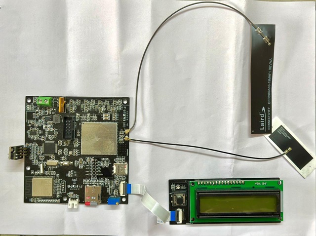
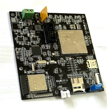
- tickӘl Board 1.0
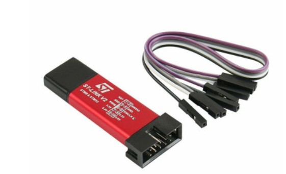
- ST Link V2 programmer
- Dc power supply+12v min 3A
- Nano Sim card
- SD card (32 GB max)
- STM32Cubeide
- tickӘl Board Library
1. Connector and Sensor Details for tickӘl Board 1.0
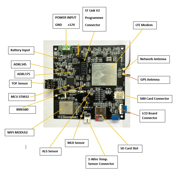
2. On-Board Sensors
Sr.no Sensor Name Part Number 1 ADXL345 ADXL345BCCZ-RL 2 ADXL375 ADXL375BCCZ-RL7 3 TOF sensor VL53L0X 4 BME680 BME680 5 ALS Sensor VEML6030 6 MLX Sensor MLX90632SLD-DCB-000-RE 7 1 wire temp Sensor DS18B20 8 Wi-Fi Module ESP32-WROOM-32D 9 LTE Module EG21GGB-128-SGNS 10 MCU STM32F070RBT6TR 11 Network Antenna (ANT1) EFF6989A3S-19MHF1 12 GPS Antenna (ANT2) 206560-0150
3. Sensor Description
a. ADXL345 – (ADXL345BCCZ-RL)
- 3-Axis, ±2 g/±4 g/±8 g/±16 g Digital Accelerometer
- Communication Protocol: I2C
- Device Address: 0x1D
- Power Supply: +3.3V_mcu
- The ADXL345 is a small, thin, ultralow power, 3-axis accelerometer with high resolution (13-bit) measurement at up to ±16 g.
b. ADXL375 – (ADXL375BCCZ-RL7)
- 3-Axis, ±200 g Digital Accelerometer
- Communication Protocol: I2C
- Device Address: 0x53
- Power Supply: +3.3V_mcu
- The ADXL375 is a small, thin, 3-axis accelerometer that provides low power consumption and high-resolution measurement up to ±200 g. The digital output data is formatted as 16-bit, twos complement data.
c. TOF Sensor – (VL53L0X)
- VL53L0x TOF based LIDAR Laser Distance Sensor
- Communication Protocol: I2C
- Power Supply: +3.3V
- The VL53L0X is a new generation Time-of-Flight (ToF) laser-ranging module housed in the smallest package on the market today, providing accurate distance measurement whatever the target reflectances, unlike conventional technologies.
- It can measure absolute distances up to 2m, setting a new benchmark in ranging performance levels, opening the door to various new applications.
d. BME680 – (BME680)
- Gas, Pressure, Humidity, Temperature sensor
- Communication Protocol: SPI
- Power Supply: +3.3V
- This sensor is used only to measure the Pressure, Humidity, Temperature values.
e. ALS Sensor – (VEML6030)
- High Accuracy Ambient Light Sensor
- Communication Protocol: I2C
- Power Supply: +3.3V_mcu
- VEML6030 is a high accuracy ambient light digital 16-bit resolution sensor in a miniature transparent 2 mm x 2 mm package. It includes a high sensitive photodiode, a low noise amplifier, a 16-bit A/D converter and supports an easy to use I2C bus communication interface and additional interrupt feature.
f. MLX90632 – (MLX90632SLD-DCB-000-RE)
- MLX90632 FIR sensor
- Communication Protocol: I2C
- Power Supply: +3.3V
- The MLX90632 is a non-contact infrared temperature sensor. Standard measurement resolution 0.02°C
g. 1 – Wire Temperature Sensor – (DS18B20)
- DS18B20 - Programmable Resolution 1-Wire Digital Thermometer
- Communication Protocol: I2C
- Power Supply: +3.3V
- The DS18B20 digital thermometer provides 9-bit to 12-bit Celsius temperature measurements. The DS18B20 communicates over a 1-Wire bus that by definition requires only one data line (and ground) for communication with a central microprocessor or microcontroller.
h. WI-FI Module – (ESP32-WROOM-32D)
- ESP32-WROOM-32D module is used for Wi-Fi functionality
- Communication Protocol: UART
- Power Supply: +3.3V
- ESP32 module is controlled by mcu for its operation. This moule will connect with available Wi-Fi network in area. Once connected to Wi-Fi network, it connects to AWS server and sends the sensor data to server in via MQTT protocol.
- THE MODULE WILL NOT CONNECT TO WIFI 5G NETWORKS.
i. LTE Modem – (EG21GGB-128-SGNS)
- Quectel EG21-G module is used for connecting with LTE network
- IoT/M2M-optimized LTE Cat 1 Module
- Communication Protocol: UART
- Power Supply: +4V
- Quectel EG21-G is an LTE Cat 1 module optimized specially for M2M and IoT applications. Adopting the 3GPP Rel.11 LTE technology, it delivers maximum data rates up to 10Mbps downlink and 5Mbps uplink
- The module once enabled, will automatically connect to LTE network available in area as per the sim card network provider.
- The network availability and network connection status is shown by two LEDs on board.
- This module communicates with mcu via UART. This module if network is available will connect to AWS server and will send sensor data to server by MQTT protocol.
- EG21 LTE module also has GPS. Once enabled by the User, location data can be viewed in data sent over to server.
4. Installing Cube Ide
Install STM32Cubeide from the link mentioned below.
5. Using tickӘl Library in STM32CUBEIDE
5.1 Launch STM32CubeIDE
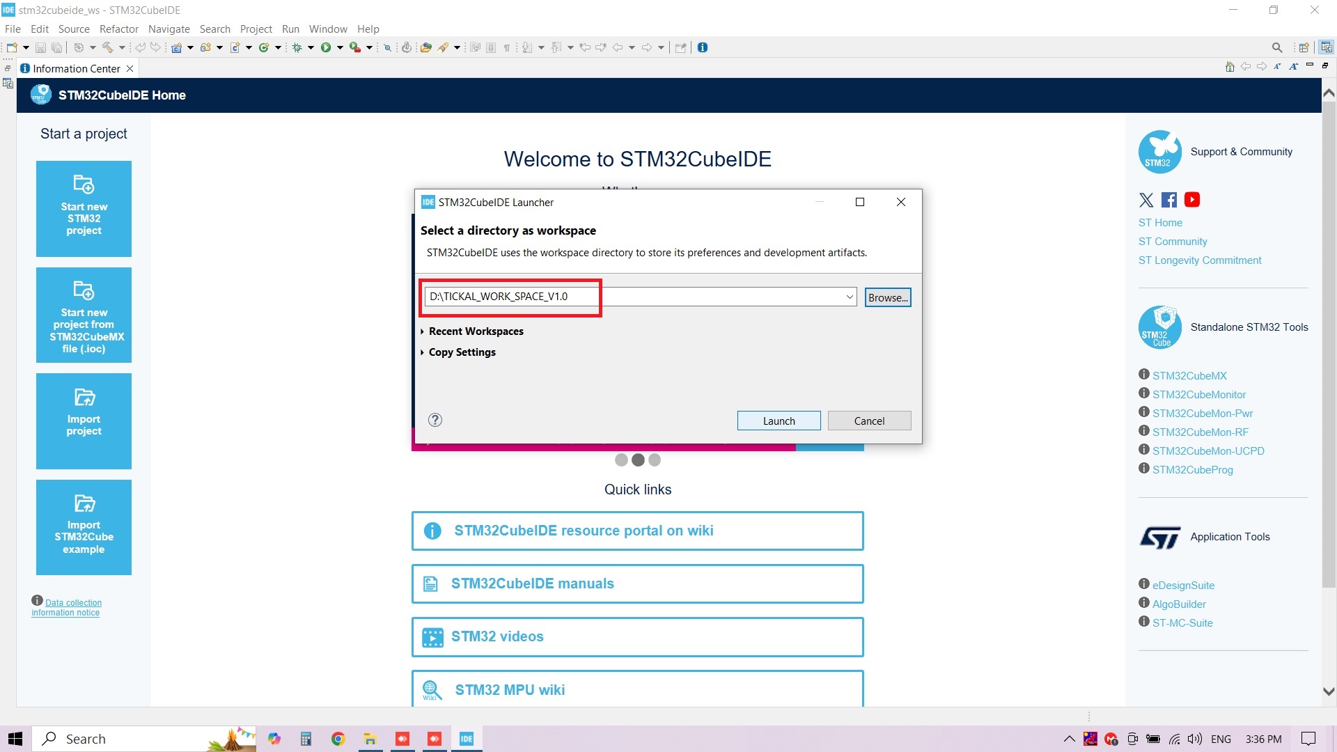
5.2 Create your own work space as shown below.
5.3 After a new workspace is created. Goto File->Import.
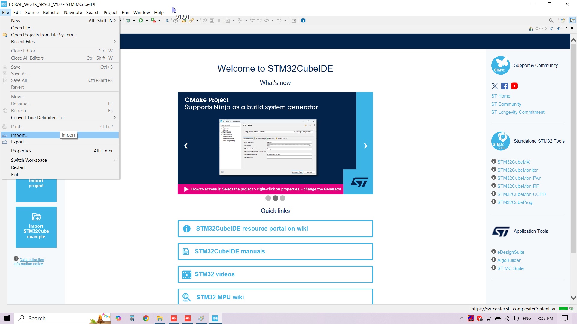
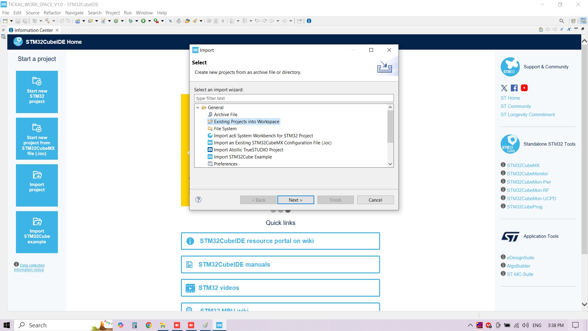
5.4 Under import option go to Import->General->Existing Project into Workspace as shown below and press Next tab.
5.5 Select option “Select archive flie”, locate the “TICKAL_BRD_LIB_V1.zip” file on your PC using the Browse tab. Select the options as shown below and press "Finish" tab.
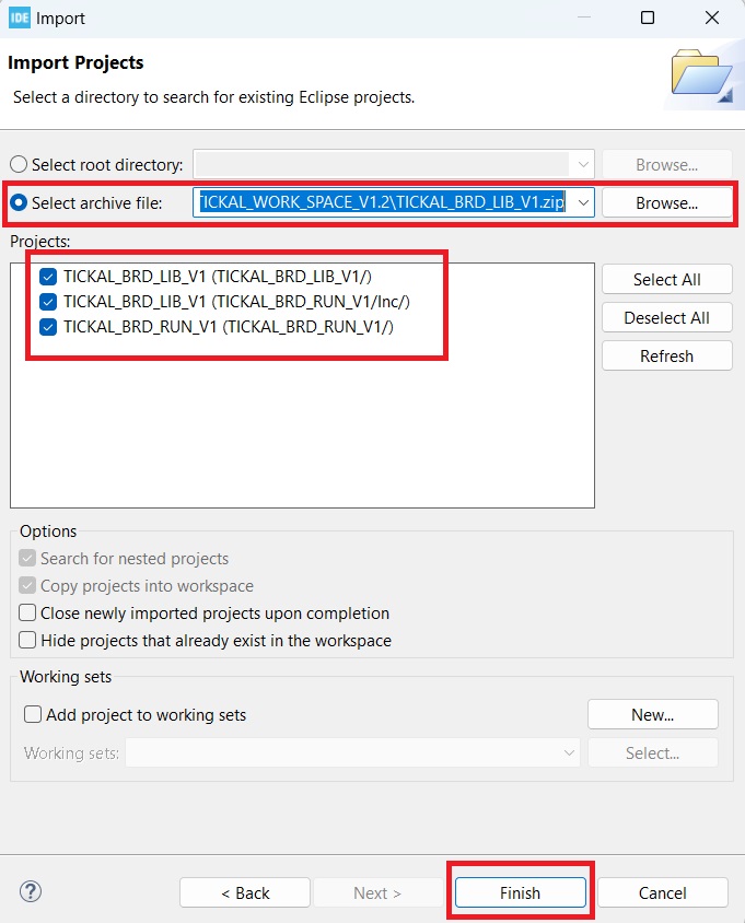
5.6 Select options as shown below.
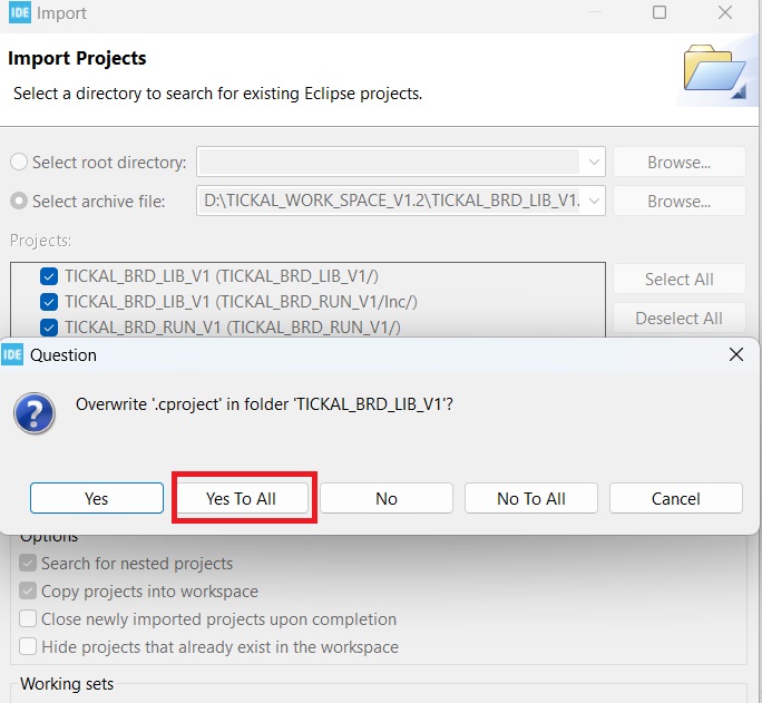
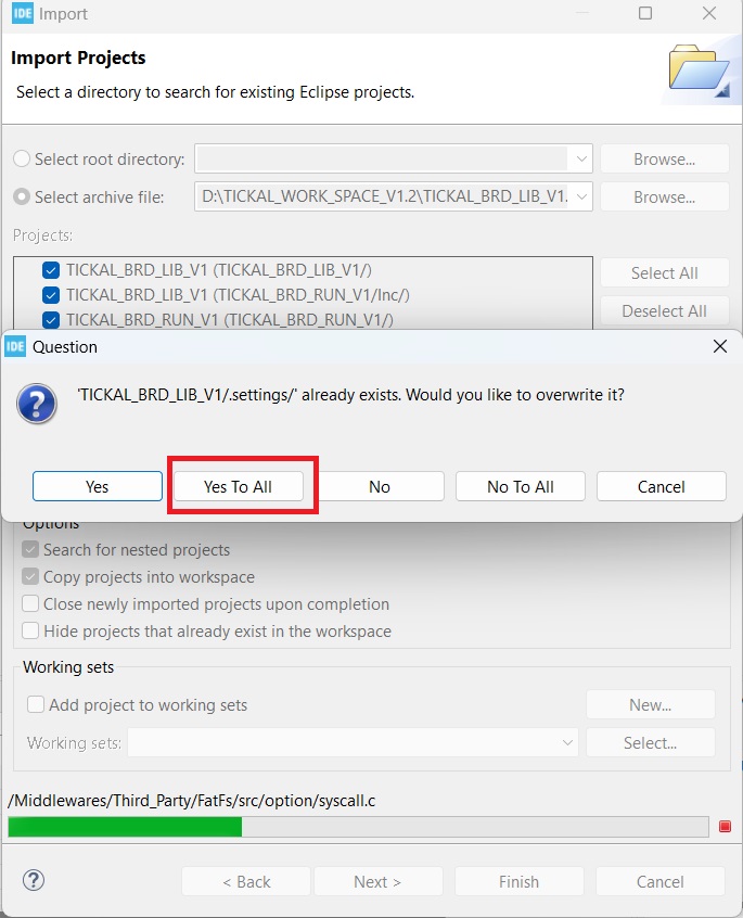
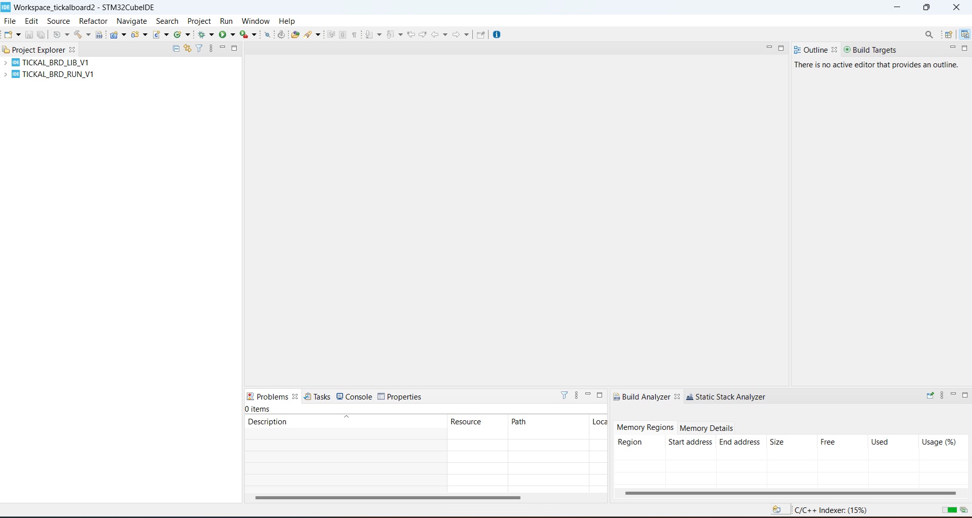
5.7 Project files and the library files for the tickӘl board are imported successfully in your workspace as shown below.
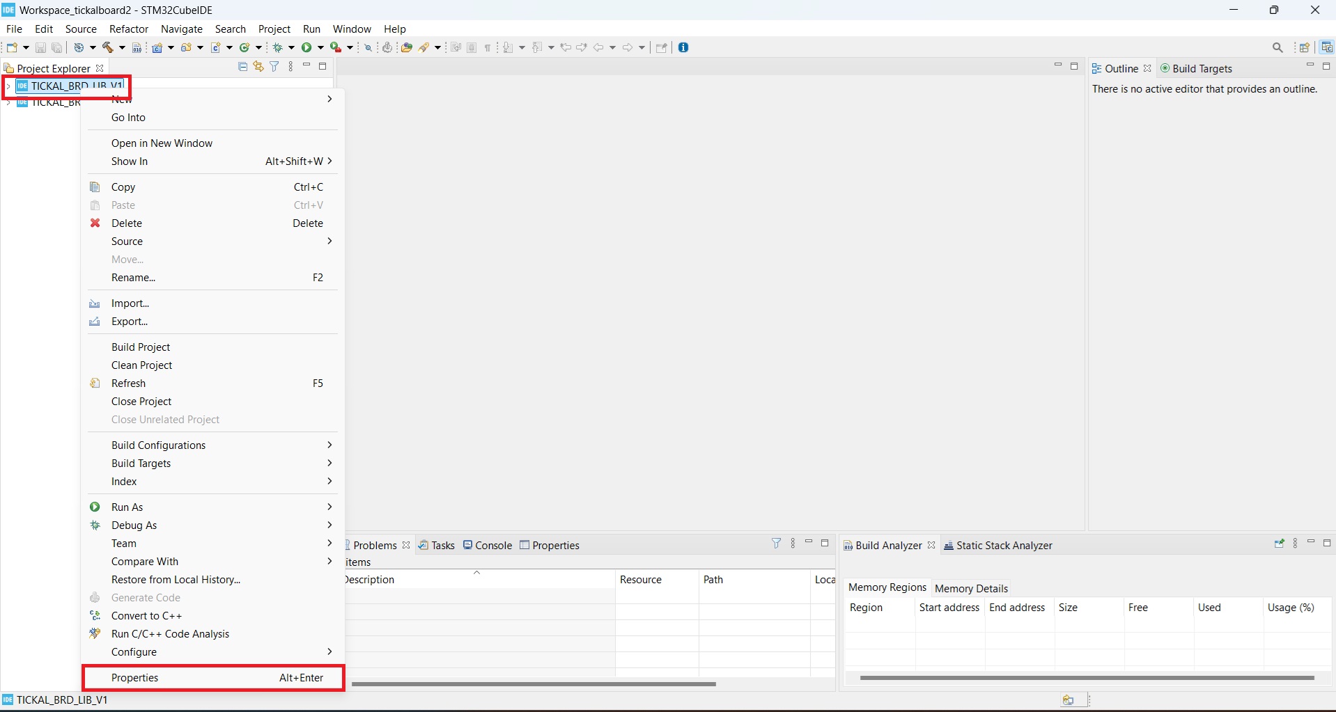
5.8 Select "TICKAL_BRD_LIB_V1" project, Right click on the project and select Properties.
5.9 Go to C/C++ Build->Settings->Tool Settings->MCU GCC Compiler->Include Paths.
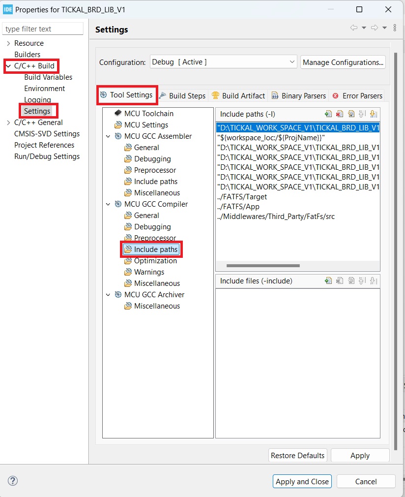
5.9 Delete all the paths mentioned in the Include Paths window.
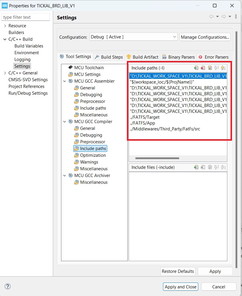
5.10 Copy the following paths and Paste them in the same window and press Apply tab.
"${workspace_loc:/${ProjName}/Core/Inc}"
"${workspace_loc:/${ProjName}/Drivers/CMSIS/Device/ST/STM32F0xx/Include}"
"${workspace_loc:/${ProjName}/Drivers/CMSIS/Include}"
"${workspace_loc:/${ProjName}/Drivers/STM32F0xx_HAL_Driver/Inc}"
"${workspace_loc:/${ProjName}/Core/Src}"
"${workspace_loc:/${ProjName}/Drivers/STM32F0xx_HAL_Driver/Inc/Legacy}"
"${workspace_loc:/${ProjName}}"
../FATFS/Target
../FATFS/App
../Middlewares/Third_Party/FatFs/src
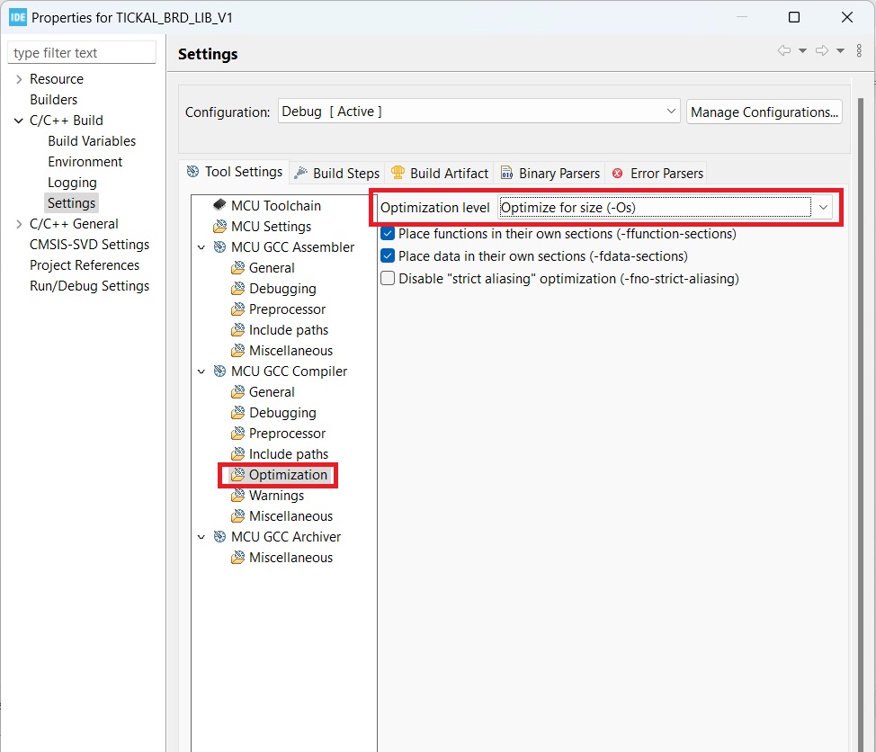
5.11 Go to C/C++ Build->Settings->Tool Settings->MCU GCC Compiler->Optimization option.
Select the option as shown below and press Apply tab.
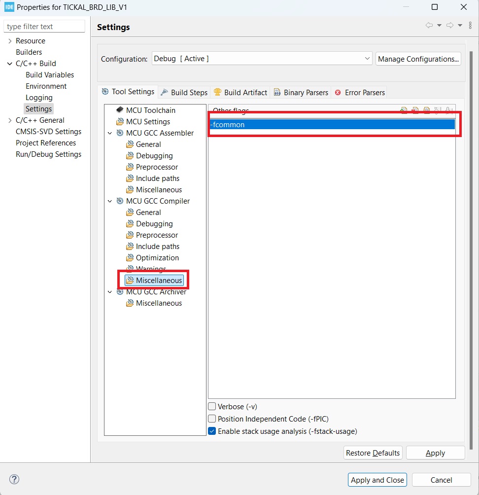
5.12 Go to C/C++ Build->Settings->Tool Settings->MCU GCC Compiler->Miscellaneous option.
Add flag "-fcommon" in the window and press "Apply and Close" tab.
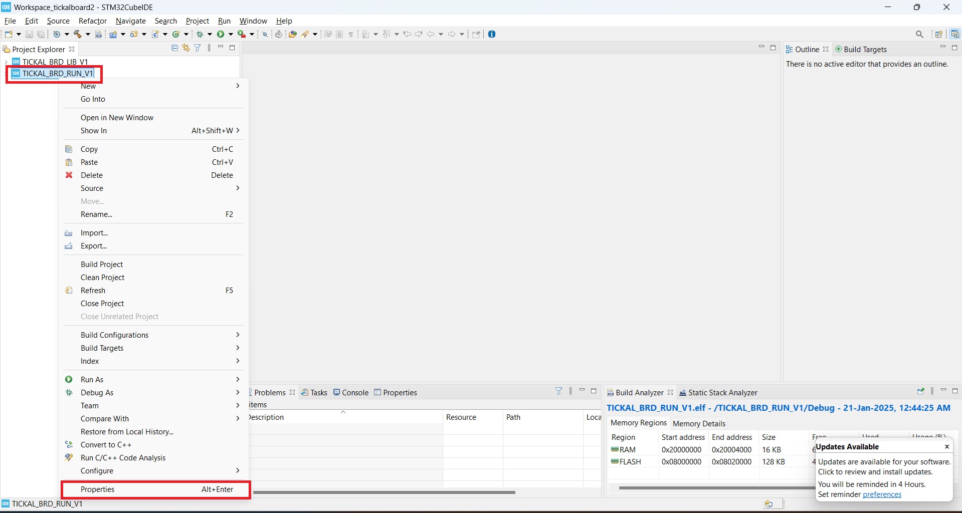
5.13 Select "TICKAL_BRD_RUN_V1" project, right click on the project and select Properties.
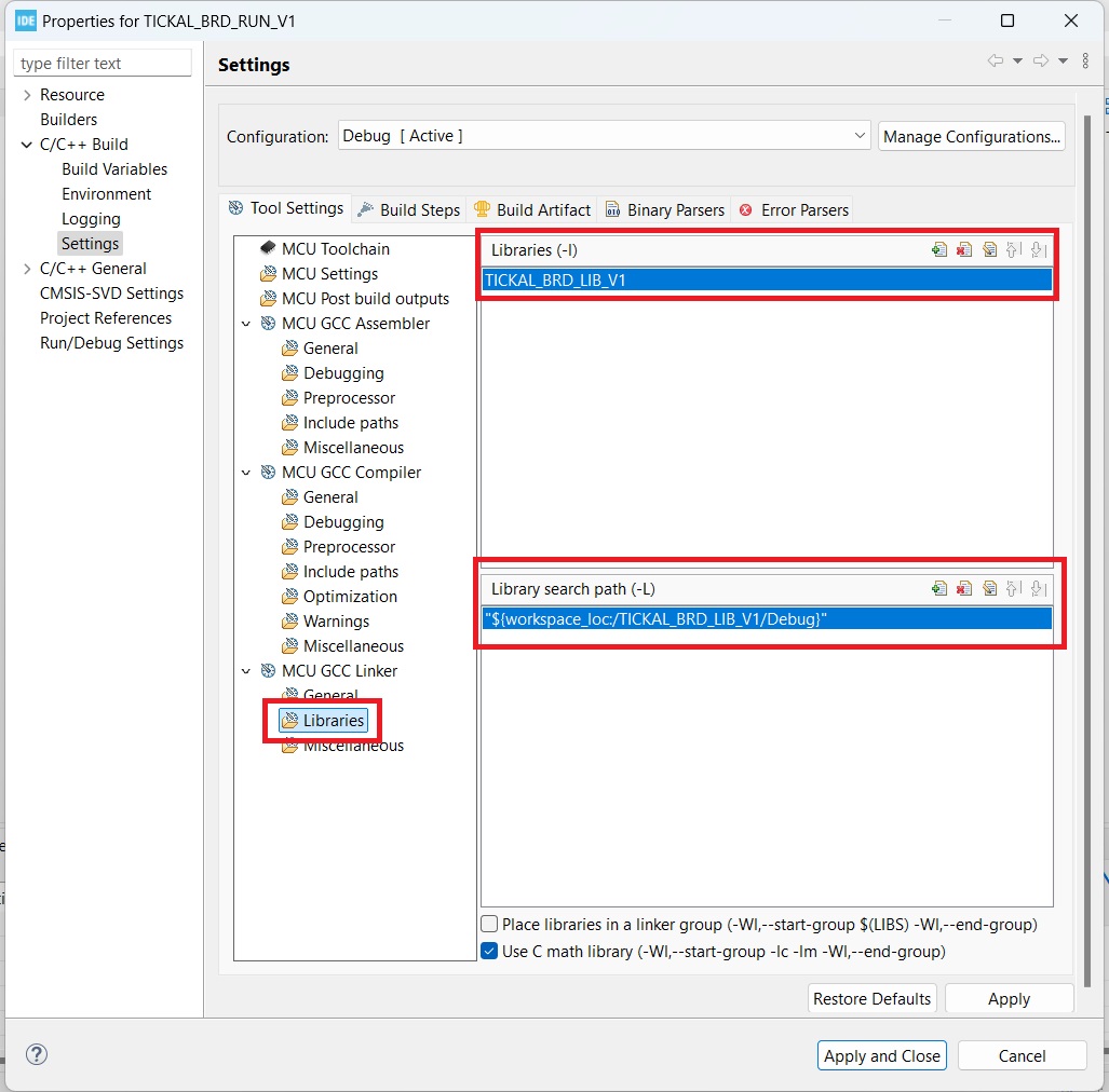
5.14 Go to C/C++ Build->Settings->Tool Settings->MCU GCC Linker->Libraries option.
Add the following library name and path as mentioned below in respective window.
Library Name : TICKAL_BRD_LIB_V1
Library Path : "${workspace_loc:/TICKAL_BRD_LIB_V1/Debug}"
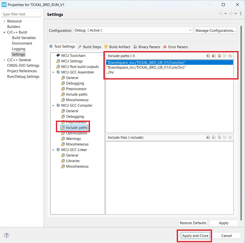
5.15 Go to C/C++ Build->Settings->Tool Settings->MCU GCC Compiler->Include Paths option.
Add the following paths as shown below.
"${workspace_loc:/TICKAL_BRD_LIB_V1/Core/Inc}"
"${workspace_loc:/TICKAL_BRD_LIB_V1/Core/Src}"
../Inc
Press "Apply and Close" tab.
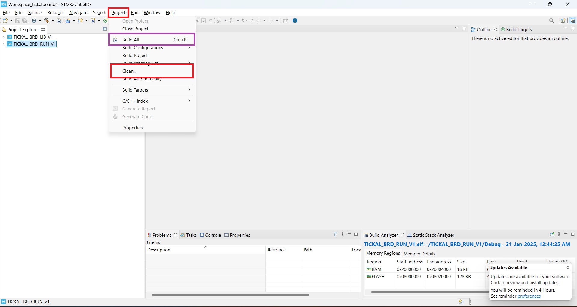
5.16 Go to Project tab first Clean the projects and then Build all the projects.
Here the library code and user code is successfully imported in STM32CubeIDE workspace.
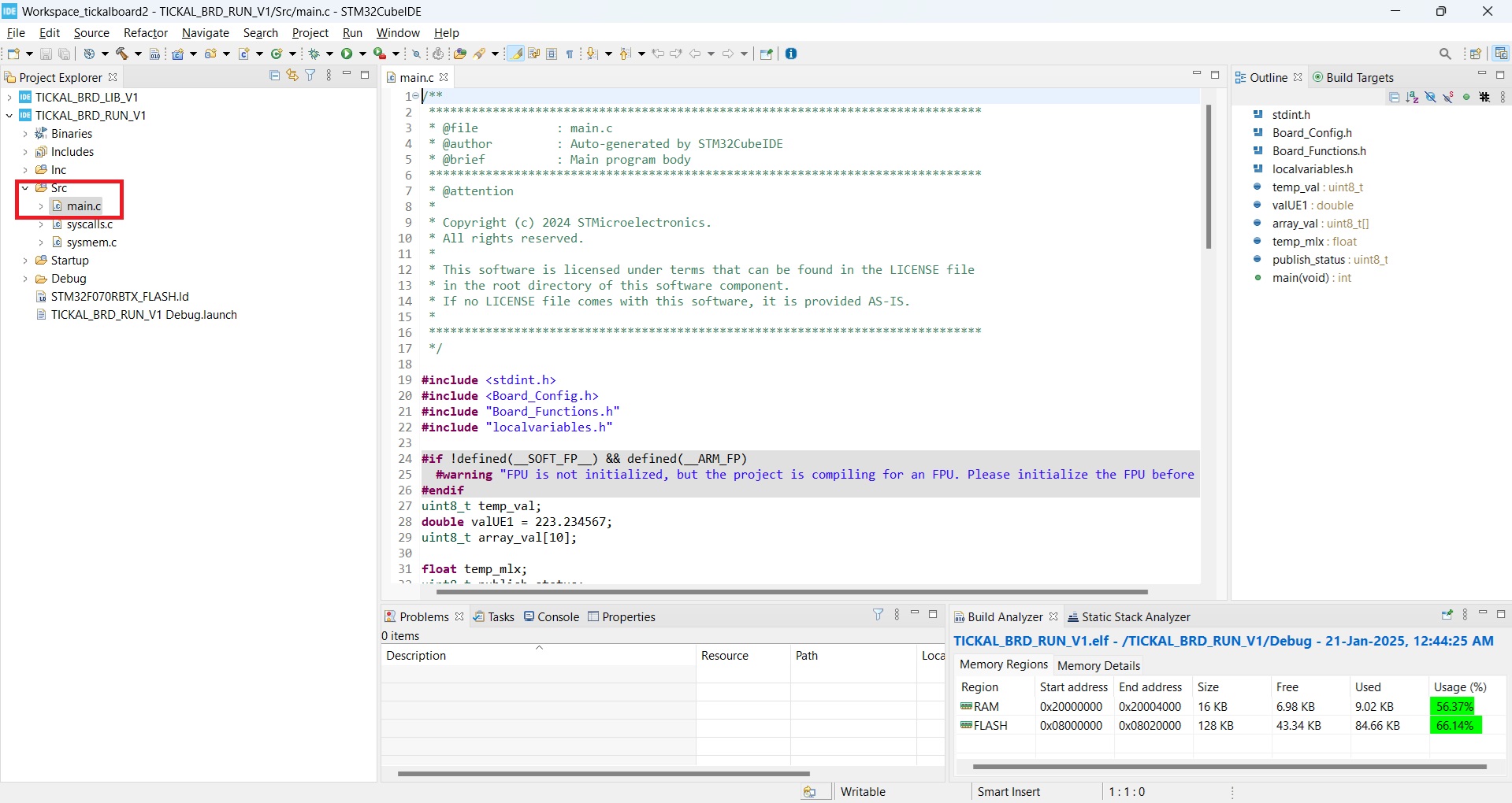
5.17 Sample project source code is available in the "main.c" file as shown below.
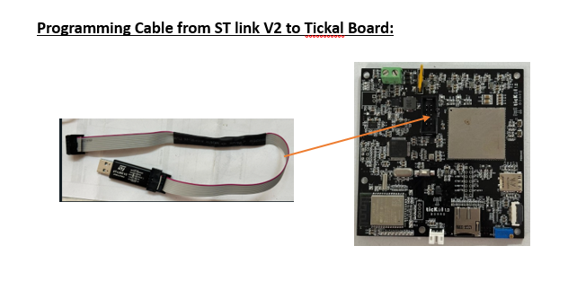
6. Hardware Connection for Downloading the code
a. ST LINK
Connection from PC to tickӘl Board for programming
7. Debug Code to tickӘl board
After building the code, user needs to press the button as shown below.
Press Run button in debug window to start code execution.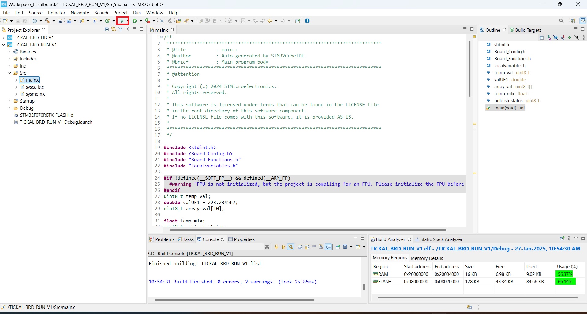
8. Check data on AWS server
a. Launch the following URL in your web browser. https://www.tickal-iot.com/login
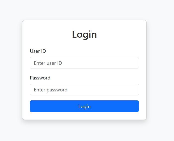
b. Following screen will be displayed
c. Login with
- User ID - admin
- Password - password123
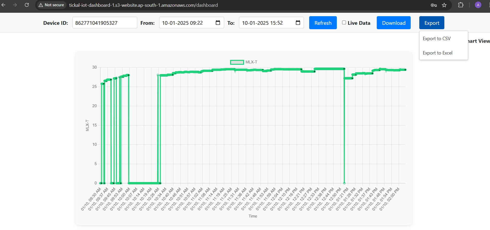
d. Following screen is displayed after login
e. Enter Device ID as mentioned on the tickӘl board.
f. After entering the Device ID, check the Live Data box and press Refresh tab
Date and time will be automatically selected and data will be displayed.
g. The data is displayed in two formats, one as graphical representation and the other in tabular format
To switch the display format, use the tab mentioned below
h. If the download tab is pressed, then the current data on the screen for all the sensors will be downloaded in json format on your computer.
i. If the Export tab is pressed , then the current data can be downloaded in .csv file or in .xlsx format on PC.
9. Command Set for tickӘl Library V1.0
1.Default function for tickӘl board
Function Name void Tickal_Start(); Function Description The basic tickӘl board function used to initialise all the peripherals on board. Function Call Tickal_Start(); Note This Function must be called only once in the main()function at the start of the code.
2.Delay Function
Function Name void Delayms(uint16_t Delay_Period); Function Description Function used to generate milliseconds delay for supplied “Delay_Period”.
Eg. User needs to pass the value 500 to the function for a delay of 500mSec.Function Call Eg. 1 – Delay of 500mSec
Delayms(500);
Eg. 2 - Delay of 3 Seconds
Delayms(3000);
Note Max value of delay that can be generated is 65.535 Seconds.
3.LED ON/OFF Functions
Function Name void Red_ON(); Function Description Function used to turn ON RED led. Function Call Red_ON(); Note
Function Name void Red_OFF(); Function Description Function used to turn OFF RED led. Function Call Red_OFF(); Note
Function Name void BLUE_ON(); Function Description Function used to turn ON BLUE led. Function Call BLUE_ON(); Note
Function Name void BLUE_OFF(); Function Description Function used to turn OFF BLUE led. Function Call BLUE_OFF(); Note
Function Name void GREEN_ON(); Function Description Function used to turn ON GREEN led. Function Call GREEN_ON(); Note
Function Name void GREEN_OFF(); Function Description Function used to turn OFF GREEN led. Function Call GREEN_OFF(); Note
Function Name void All_Led_Off(); Function Description Function used to turn OFF all LEDS. Function Call All_Led_Off(); Note
4.LED Toggle Functions
Function Name void Toggle_RED(uint16_t Toggle_Period); Function Description Toggle RED led with the provided “Toggle_Period” value in milliseconds. If the user needs to toggle the RED led every 100mSec, pass 100 as Toggle_Period. Function Call Eg. 1 – Toggle RED led for each 250mSec
Toggle_RED(250);Note Max value of toggle period is 65535.
Function Name void Toggle_RED_STOP(); Function Description Stop RED Led toggle. Function Call Toggle_RED_STOP(); Note
Function Name void Toggle_GREEN(uint16_t Toggle_Period); Function Description Toggle GREEN led with supplied “Toggle_Period” value in milliseconds. If the user needs to toggle the GREEN led every 100mSec, pass 100 as Toggle_Period. Function Call Eg. 1 – Toggle GREEN led for each 250mSec
Toggle_GREEN(250);Note Max value of toggle period is 65535.
Function Name void Toggle_GREEN_STOP(); Function Description Stop GREEN Led toggle. Function Call Toggle_GREEN_STOP(); Note
Function Name void Toggle_BLUE(uint16_t Toggle_Period); Function Description Toggle BLUE led with supplied “Toggle_Period” value in milliseconds. If the user needs to toggle the BLUE led every 100mSec, pass 100 as Toggle_Period. Function Call Eg. 1 – Toggle BLUE led for each 250mSec
Toggle_BLUE(250);Note Max value of toggle period is 65535.
Function Name void Toggle_BLUE_STOP(); Function Description Stop BLUE Led toggle. Function Call Toggle_BLUE_STOP(); Note
5.LCD Functions
Function Name void Start_LCD_Backlight(void); Function Description Turns ON the backlight for LCD Function Call Start_LCD_Backlight(); Note
Function Name void Stop_LCD_Backlight(void); Function Description Turns OFF the backlight for LCD Function Call Stop_LCD_Backlight(); Note
Function Name void LCD_Erase(void); Function Description Clear both lines on LCD Function Call LCD_Erase(); Note
Function Name void LCD_Line_Clear(uint8_t Line_number); Function Description This function will erase the Line number passed as parameter to function. Function Call 1. Erase LINE 1
LCD_Line_Clear(1);
2. Erase LINE 2
LCD_Line_Clear(2);Note
Function Name uint8_t Disp_Str(uint8_t Line_number,uint8_t Col_number,unsigned char *var); Function Description Display a string on LCD. Pass the Line number, column number and the string to the function to display it on the LCD. Function Call Eg. 1 – Display “Tickal Board” at Line 1 and column 0 position
Disp_Str(1,0,”Tickal Board”);Note The max number of characters which can be displayed on each line is 16.
If the length of the string exceeds position, the function returns “2” indicating string length mismatch.Return value:
“1” = String Length is correct and will be displayed on LCD
“2” = String length mismatch and will not be displayed on LCD
Function Name uint8_t Disp_float(uint8_t Line_number,uint8_t Col_number,double val,uint8_t decimal_pos); Function Description Display float values on the LCD. Pass the line number, column number, and the float value to be displayed and the max positions after decimal point to be displayed on the lcd. Function Call Display 19.3427 row 2 and col number 4 and display only 2pos after decimal.
float test1;//define variable test1
test1 = 19.3427; //variable that contains the float value to be displayed
Disp_float (2,4, test1,2); //function call to display the given number
Note Max 4 decimal positions can be displayed on the LCD and Min. 1 decimal position can be displayed on the LCD.
Max float value that can be displayed is xxx.xxxx i.e 999.9999Return value:
“1” = Float value passed is within limits and is displayed on LCD
“2” = Float value passed is not within limits and not displayed
Function Name uint8_t Disp_number(uint8_t Line_number,uint8_t Col_number,uint32_t disp_number); Function Description Display decimal values on the LCD. Pass the line number, column number, and the value to be displayed on the lcd. Function Call Display 23487 row 2 and col number 4
uint32_t test1;
test1 = 23487; //variable that contains the value to be displayed
Disp_number (2,4, test1); //function call to display the given number
Or Directly pass the number to function
Disp_number (2,4, 23487); //function call to display the given numberNote Max number that can be displayed is xxxxxx i.e 999999 Return value:
“1” = Float value passed is within limits and is displayed on LCD
“2” = Float value passed is not within limits and not displayed
6.TOF Sensor
Function Name uint16_t ReadTOF(); Function Description The function reads the current distance value from TOF sensor in mm and returns it to the user. Function Call uint16_t distance_val;
while(1)
{
distance_val = ReadTOF();
}Note User must define a variable in which current distance value will be returned as demonstrated above in the example.
The distance is measured from the on-board sensor till a white reflective surface in front of the sensor. If any other colour surface is used, the distance value read by the sensor might not be correct.Return value:,
In case a invalid value is received from TOF sensor, user should call the ResetTOF(); //function to restart the device.
Function Name uint8_t ResetTOF(); Function Description This function is used to reset the TOF sensor. Function Call uint8_t Status_reset_TOF;
Status_reset_TOF = ResetTOF();Note In case if the function returns “0” to user, the same function should be called again. Return value:,
“1” = Reset of TOF sensor is successful
“0” = Reset of TOF sensor is not complete
7.MLX90632 Temperature Sensor
Function Name void ReadMLX(); Function Description Function is used to read the MLX sensor. This function returns both, the object temp and the ambient temp float values in SensorMLX.Object , SensorMLX.Ambient variables Function Call ReadMLX(); Note User User is not required to define any variable for reading the MLX sensor. The float values are already declared in the library. As per observation, sensor reads random values at start. After multiple readings of sensor actual temperature values are measured. Return value:,
SensorMLX.Object = Object temperature value
SensorMLX.Ambient = Ambient temperature value
Function Name uint8_t MLX_Restart(); Function Description Function is used to reset the MLX sensor. If this function returns value ‘1’, it indicates the sensor is reset and communication is established .If it returns '0' indicating sensor communication failure and the sensor is not initialized. This status is available to user in SensorMLX.CommunicationStatus variable. Function Call uint8_t status;
status = MLX_Restart();Note User can define a separate variable to read the reset status or it is already available in SensorMLX.CommunicationStatus Return value:,
“1” = Sensor reset successful
“0” = Sensor reset not successful
8.BME680
Function Name void ReadBME(); Function Description Function is used to read the BME680 sensor. The sensor reads temperature, humidity and pressure values.
This functions returns temp., humidity ,pressure values in SensorBME.Temperature,SensorBME.Humidity,SensorBME.Pressure variables respectivelyFunction Call ReadBME(); Note Return value:
SensorBME.Temperature = Temperature value returned by BME680
SensorBME.Humidity = Humidity value returned by BME680
SensorBME.Pressure = Pressure value returned by BME680
Function Name uint8_t BME_Restart(); Function Description Function is used to reset the BME680 sensor. If this function returns the value '1' .it indicates that the BME680 sensor is reset and communication is established. If it returns '0' it indicates the BME680 communication failure and that the sensor is not initialized. This status is available to user in SensorBME.CommunicationStatus variable. Function Call BME_Restart(); Note User can define a separate variable to read the reset status or it is already available in SensorBME.CommunicationStatus Return value:,
“1” = Sensor reset successful
“0” = Sensor reset not successful
9.ADXL375
Function Name void ReadADXL375(); Function Description Function is used to read the ADXL375 sensor. The function reads both raw values as well as the converted ‘g’ values from the ADXL375 sensor. The values are
SensorADXL375.RAW_X
SensorADXL375.RAW_Y
SensorADXL375.RAW_Z
SensorADXL375.G_X
SensorADXL375.G_Y
SensorADXL375.G_Z
Function Call ReadADXL375(); Note User is not required to define any variable for reading the ADXL375 sensor. The float and the raw values are already present in predefined variables. Return value:
SensorADXL375.RAW_n = 16 bit raw value of register in X, Y or Z direction.
SensorADXL375.G_n = Actual float value in X, Y or Z direction.
Function Name void InitADXL375(void); Function Description Function is used to initialise the ADXL375 accelerometer. Communication status is available in the variable SensorADXL375.chip_present. Function Call InitADXL375(); Note User can define a separate variable to read the init status or it is already available in SensorADXL375.chip_present Return value:,
SensorADXL375.chip_present = 1; //Sensor Available
SensorADXL375.chip_present = 0 ; // Sensor is not Available
10.ADXL345
Function Name void ReadADXL345(); Function Description Function is used to read the ADXL345 sensor. The function reads both raw values as well as the converted ‘g’ values from the ADXL375 sensor. The values are
SensorADXL345.RAW_X
SensorADXL345.RAW_Y
SensorADXL345.RAW_Z
SensorADXL345.G_X
SensorADXL345.G_Y
SensorADXL345.G_Z
Function Call ReadADXL345(); Note User is not required to define any variable for reading the ADXL345 sensor. The float and the raw values are already present in predefined variables. Return value:
SensorADXL345.RAW_n = 16 bit raw value of register in X, Y or Z direction.
SensorADXL345.G_n = Actual float value in X, Y or Z direction.
Function Name void InitADXL345(void); Function Description Function is used to initialise the ADXL375 accelerometer. Communication status is available in the variable SensorADXL345.chip_present. Function Call InitADXL345(); Note User can define a separate variable to read the init status or it is already available in SensorADXL345.chip_present Return value:,
SensorADXL345.chip_present = 1; //Sensor Available
SensorADXL345.chip_present = 0 ; // Sensor is not Available
11.LTE/GPS modem
Function Name uint8_t Start_Modem(void); Function Description Function is used to start the LTE/GPS modem. This function starts LTE/GPS modem and configures the basic settings of the modem and returns the status back to the user. Function Call uint8_t Init_Status;
Init_Status = Start_Modem ();Note User is required to define one variable to read back the init status of LTE/GPS modem. Return value:,
“1” = LTE init successful
“0” = LTE not init
Function Name uint8_t Connect_Server_LTE(void); Function Description Function connects the LTE/GPS modem to the AWS server and returns the connection status back to the user. Function Call uint8_t Connection_State;
Connection_State = Connect_Server_LTE ();Note User is required to define one variable to read back the connection status between the modem and the AWS server. In case user receives back the value for a failed connection, the same function should be called again to connect to the AWS server. Return value:,
“1” = Connection with AWS server successful
“0” = Connection with AWS server failed
Function Name uint8_t Start_GPS(void); Function Description Function is called to start the GPS on the LTE/GPS modem. Function Call uint8_t GPS_State;
GPS_State = Start_GPS ();Note This function starts the GPS on LTE modem and returns GPS module running status back to user. User should define a variable as mentioned above to check if GPS has started or not. Return value:,
“1” = GPS started
“0” = Start GPS failed
Function Name uint8_t Publish_Data_LTE(void); Function Description This function publishes the data to the AWS server in JSON format. Corresponding data is published on the AWS server based on the flags set in the TICKAL_CONFIG.h header file. This function returns the publish status back to the user. Function Call uint8_t Publish_State;
Publish_State = Publish_Data_LTE ();Note The user is required to define one variable to read back the data publish status between the modem and the AWS server. Return value:,
“1” = Data published to AWS server successful
“0” = Data published to AWS server failed
Function Name void Restart_Modem(void); Function Description Function is called to reset the LTE/GPS modem. This function resets the PWRKEY pin of the modem Function Call Restart_Modem(); Note No need to define any variables for this function. After calling this function user should call the start_modem(); function to start the basic functionality of LTE modem.
12.ALS Sensor – VEML6030
Function Name void ReadALS(void); Function Description This function reads both white light and Ambient light values from the VEML6030 sensor. These values are available in SensorALS.als, SensorALS.white variables. Function Call ReadALS(); Note User is not required to define any variable to get both white light and ambient light values. The ALS sensor returns 16 bit value back to user for both white light and ambient light. If sensor is covered or is in dark room both values are closer to 0. Return value:
SensorALS.als = Ambient light sensor value
SensorALS.white = White light sensor value
13.DS18B20 Temperature Sensor
Function Name void ReadDS18b20(void); Function Description This function reads temperature value from the 1-wire sensor. Function Call ReadDS18b20 (); Note User is not required to define any variable. The temperature value is available to user in SensorDS18b20.Temperature variable. Return value:
SensorDS18b20.Temperature = Temperature value of DS18B20
14.WI-FI
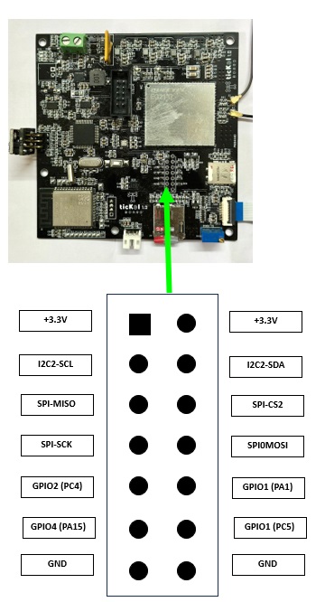
Name WI-FI Credentials Function Description User can define the WI-FI connection credentials in localvariables.h file in TICKAL_BRD_RUN_V1 project. Function Call //========= localvariables.h file ==========
char SSID[25] = "XXXXXX";
char PASSWORD[25] = "XXXX";
Note Max length for both SSID and Password is 25 bytes.
Function Name void Connect_WIFI(void); Function Description Function connects to a WI-FI network as per given credentials. Function Call Connect_WIFI(); Note If the user has defined the WIFI_CRED variable as “0”, then this function first collects the SSID and password from the user and then connects to the Wifi network. User must follow the instructions provided on the LCD screen for connecting to the static server page created by the WI-FI module. The IP address for the static page is “192.168.4.1:5000” where 5000 is port. THE WIFI DEVICE DOES NOT CONNECT TO 5G NETWORK
Function Name uint8_t Connect_WIFI_to_Server(void); Function Description Connect the WI-FI module to the AWS server Function Call uint8_t Wifi_Connect_status;
Wifi_Connect_status = Connect_WIFI_to_Server ();Note User should define one variable to get the connection status between WI-FI module and the AWS server. Return value:
“1” = Connected to AWS server
“0” = Connection with AWS server failed
Function Name void Publish_Data_Wifi(void); Function Description Publish data to the AWS server. Function Call uint8_t Wifi_Publish_status;
Wifi_Publish_status = Publish_Data_Wifi ();Note User is required to define one variable to read back the data publish status between WI_FI and the AWS server Return value:
“1” = Data published to AWS server successful
“0” = Data published to AWS server failed
15.SD Card
SD card is enabled in the library code by default. In Tickal_Start(); function mcu checks if the SD card is present or not
If SD card is detected,Tickal_Start() function automatically mounts the SD card and creates a file “TData.csv” file on the SD card.
For each power-on, a new file is created and the old file is deleted.
Function Name uint8_t ClearSDcard(void); Function Description Clear SD card function used to delete old file “TData.csv” Function Call uint8_t flagchk;
flagchk = ClearSDcard ();Note User should define one variable to check if file is deleted or not. Return value:
“1” = File deleted successfully
“0” = File is not deleted
Function Name uint16_t UpdateSDcard(void); Function Description Function opens the file “TData.csv” file and appends the new data in this file. Function Call UpdateSDcard (); Note The function returns the current number of records written on the SD card. If required, the user can define one variable and read this value.
DATA STORED IN SD CARD AS FOLLOWS
Function Name void ReadSDCard(uint16_t record_number); Function Description Read the record from SD card based on the input received from the user. Function Call ReadSDCard (22); Note The function reads the record number 22 from the SD card. The read record is available for the user in sd_Card_Array[200] array, no need to define any new array for this.
15.User Key
Function Name uint8_t User_Key_Flag; Function Description This flag is predefined in code to get the status of the key pressed by user. If the user presses the key, the value for User_Key_Flag is 1 else it is 0; Function Call If(User_Key_Flag == 1)
{
User_Key_Flag = 0;
//======= user test code =======================
}Note This function checks falling edge interrupt for a key press, if the falling edge interrupt is detected ,the User_Key_Flag is set to “1” in the Interrupt Service Routine (ISR)
Function Name void WaitTillKeyPressed(void); Function Description Wait till key is pressed Function Call If(User_Key_Flag == 1)
{
User_Key_Flag = 0;
//======= user test code =======================
WaitTillKeyPressed(); }Note Code waits at the same location unless the key is released by the user
16.Sleep Mode
Function Name void Check_Power(void); Function Description If DC voltage input is not present on the board, this function puts the MCU in SLEEP mode.
The MCU wakes up from SLEEP mode, if either the user presses the User key or if DC voltage input is restored on the board.In SLEEP mode, all power on the board Is disabled. Only power to both ADXL345 and ADXL375 is enabled and mcu is in stop mode. Approximate current used by tickӘl board is around 90uAmps. .Function Call while(1)
{
//---------- user code --------------
Check_Power();
}Note On Wakeup from sleep, all the sensors are re-initialised except WiFi and LTE/GPS modules.
User must call the respective functions for LTE/GPS and the WiFi to connect to the AWS server for data transfer. In case of wakeup, if user key is pressed by user to wakeup and DC input is not present, mcu will check the main code once goes back to sleep again.
17.1msec Timer
Function Name void HAL_TIM_PeriodElapsedCallback(TIM_HandleTypeDef *htim); Function Description User is provided with one interrupt based timer in the file interrupt_functions.h. This is a 1 mSec timer. User can write any code inside as shown below, this code will be executed every 1 mSec. Function Call //-------- in interrupt_functions.h file
void HAL_TIM_PeriodElapsedCallback(TIM_HandleTypeDef *htim)
{
if (htim == &htim14 )
{
//-----------User code -------------------
user1msec++;
if(user1msec > 9)
{
user1msec = 0;
user10msec++;
}
}
}Note Do not change any name or syntax of this function.
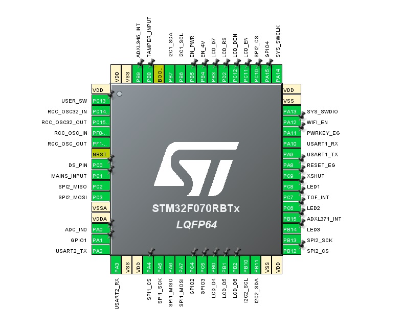
10. MCU Pinout
11. Download tickӘl BSP